|


| |
|
Summary
In this discussion about
delta-shaped and related sails, experiences with prototype sails are
described first. The sails have a forgiving nature, providing
significant lift as well as propulsion when sailing off the wind,
and produce a relatively small heeling force. The results of a
numerical simulation carried out by Adam Ryan are then summarised.
In a discussion about the aerodynamics of sails (and wings) that
have a conical or truncated conical form, it is hypothesised that
vortex production from the tip of the sail is minimised by the
curvature of the upper part of the sail to windward, by sweepback,
and by washout. It appears that delta-shaped sails are particularly
effective because of the way they manage airflow across them in
three dimensions. |
|
Definition
A delta-shaped sail has a highly-raked (ie: 40ş or more from the
vertical) leading edge supported either by a spar or a stay, a foot
that is approximately parallel to the surface of the water, and a
trailing edge that is approximately vertical.
There are several traditional
sailing rigs that carry delta-shaped sails, for example the Lateen
and Crab-Claw. A proportion of Jibs, Genoas, and Asymmetric
Spinnakers could also be considered within the category of
delta-shaped sails as broadly defined above. There are other rigs
that carry sails conforming partially to the conical geometry of
delta-shaped sails, for example Lug, Junk, Gaff, and Transition rigs
– these will be referred to in this discussion as truncated
deltas. |
|
Introduction
The inspiration for this
investigation into delta-shaped sails came from watching films of
Australian 18-foot skiffs (‘Awesome Aussie Skiffs’ 1 and 2).
These lightweight boats carry a crew of three who can trapeze out
from the extensive wings on each side of the boat and carry a
proportionately large sail area. In suitable conditions the Aussie
skiffs are capable of planing on most points of sail. Sailing
downwind, the crew hoists a large asymmetric spinnaker supported
from a forestay and the craft follows a rapid zig-zag downwind
course gybing from tack to tack. From viewing the films, it became
clear that the spinnaker – in addition to generating considerable
forward power - also generates lift, holding the bow of the craft up
out of the water and reducing the risk of nose-diving into the back
of a wave in front. |
|
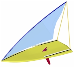
Figure 1:
Idea for Concept Boat
competition entry |
At
the time, I was developing an entry for the Concept Boat 2005
competition. The brief was to design a craft that would encourage
families out onto the water, and I was working with the idea of a
lightweight craft that could be carried on top the car and that
would be simple to sail. I decided that a simple sailboard-like
craft would be best, with additional volume (and hence buoyancy) to
support additional family members. After considering different
sailing rigs, including standard sailboard rigs, I came up with the
idea of a delta-shaped sail with a raked, curving spar supporting
the leading edge of the sail and an A-frame from the back of the
craft supporting the aft tip of the spar (Figure 1). |
|
Test rig
To test the performance of this
sail before continuing further with the design concept, I made a
test rig for a Fireball dinghy. The spar carrying the sail was made
from aluminium tubing bent into a curve and stiffened with spiral
layers of carbon tape embedded in epoxy resin. The A-frame was made
from aluminium tubing and supported from an aluminium cross-tube at
the stern of the dinghy. The sail was cut from an existing Fireball
sail and a mast sleeve added along the new leading edge. The curve
of the leading edge of the sail exactly matched the curve of the
spar so that when it was rigged in still air it hung flat below the
spar without any built-in camber. Three horizontal battens were
added. These were made from tapered carbon-fibre tubes (fishing
rods) which narrowed towards the leading edge. The main sheet was
attached to the clew of the sail and acted around a rope traveller
tied to the ends of the cross-tube. This arrangement allowed
trimming tension to be applied to the sail both downwards and
backwards. |
|
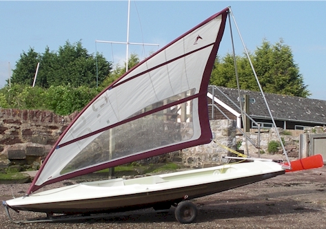
Figure 2:
Sail filling and lifting due to airflow across it |
Onshore with the rig aligned appropriately towards
the wind, it was clear that the unrestrained sail had a tendency to
billow to the side and lift up (Figure 2). As it billowed,
curvatures appeared both from front to back across the sail
(horizontal camber) and from top to bottom (vertical camber). As a
consequence of the curvature of the mast, the more the originally
flat sail moved out to the side, the greater this ‘ballooning’
effect became. This can best be understood by thinking about the
situation where the sail has lifted until it is flying almost
horizontally alongside the spar. In this position, looked at from
above, the spar appears straight and the curved leading edge of the
sail has to conform with it. This results in slackening of the cloth
between the mid region of the spar and the foot of the sail,
encouraging cambers to form. This adaptive change in the sail from
being relatively flat when sailing close-hauled to being more curved
when sailing off the wind contributed to its effectiveness. |
|
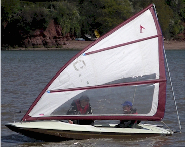
Figure 3:
Sailing upwind
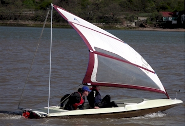
Figure 4:
Sailing off the wind |
On the water, the rig performed well (Figures 3 and
4). The spar and A-frame provided a stable, interference-free
support for the sail. Compared with more conventional rigs, the low
aspect-ratio sail with its correspondingly low centre of effort
reduced the capsizing moment produced by gusts and stronger winds,
giving the dinghy a more stable feel. In conditions ranging from
Force 2 to Force 4 it was relatively easy to set a course and
maintain it, and the sail seemed tolerant of sheeting angles. The
dinghy could be sailed on all the usual points of sail, although it
was noticeably slower on a dead run downwind, particularly in
lighter winds. This was probably due to the reduced area presented
to the wind by the fully-sheeted out sail. Under these conditions
most of the wider aft parts of the sail were flying out almost
horizontally to the side of the upper third of the spar, and the
wind was being directed forward mainly onto the narrower, more
vertical part of the sail near the bow. |
|
To learn more about the airflow across and behind the
sail, woollen tell-tales were attached in a grid-like pattern across
both surfaces of the sail and streamers attached to the trailing
edge at the top of the sail and at batten locations. It could be
seen that on the windward side of the sail, the airflow in the
vicinity of the surface was being deviated somewhat upwards as it
passed from leading to trailing edges. The streamer at the top of
the sail streamed smoothly behind with very little fluttering
compared with the streamer at the foot of the sail. |
|
Modifications to the rig
concept
With the experience gained from the test rig, it was possible to
return to the design of the rig for Concept Boat competition entry.
To enhance the downwind capability in light airs, I decided to have
a double-skinned sail that could be opened out like a spinnaker when
required, doubling its area (Figure 5, a). On other points of sail,
the two laminae of the sail would remain together (Figure 5, b). |
|
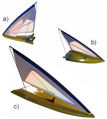
Figure 5:
Different rig configurations – a) sailing downwind with sail laminae
separated, b) normal sailing with laminae together, c) sail reefed
and A-frame feet moved forwards to lower spar and bring sail foot
close to hull |
This double-layered approach opened a new possibility for reefing.
The batten layout was changed – a lower batten was positioned along
the foot of each sail lamina, and then an upper batten was
positioned from the front lower tip of each lamina obliquely across
the sail to the mid-point of the trailing edge. For reefing, the
lower segment of each lamina could then be folded up in between the
two laminae and fixed in position so that the upper batten becomes
the new sail foot. The sheet for the sail would then be moved to
eyelets adjacent to the ends of the upper battens. The sail, now
halved in area, could be used either in its normal position to give
greater headroom for those on board, or lowered for high-wind use by
sliding the feet of the A-frame forwards along the side tubes until
the new foot of the sail is close to the board (Figure 5, c). |
|
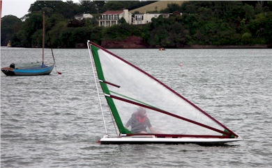
Figure 6:
Flčche going upwind
with the sail laminae together
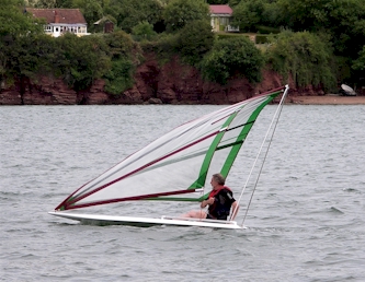
Figure 7:
Flčche going down wind
with the sail laminae separated |
Prototype Flčche
A prototype Flčche was made. Initial test
sailings indicated that a rigid traveller across the stern was
needed for the main sheet, but in general the concept worked well
(Figure 6). Sailing downwind with the two sail laminae separated
proved to be effective (Figure 7). |
|
Numerical study of the
Flčche rig
Adam Ryan, a student studying
for a sports science degree at the University of Plymouth, modelled
the properties of the Flčche rig using computational fluid dynamics
(CFD). CFD is a method that employs the equations of fluid mechanics
to describe a flow field on and around a surface. By numerically
modelling the shape being studied and placing it within a defined
fluid domain, the flow field characteristics can be calculated. To
simplify the calculations, the leading edge spar, battens, changing
sail shapes under load, and the relationship of the sail with the
hull were not modelled, so the results have to be interpreted with
this in mind. |
|
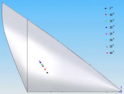
Figure 8:
Movement of the centre of effort at
different angles of incidence (from Ryan 2007) |
The simulated sail was studied at different angles of
incidence to the airflow from 5ş to 40ş. The sail produced a maximum
CL (coefficient of lift) at around 30ş, beyond which the
sail stalled and the CL rapidly dropped off whilst the CD
(coefficient of drag) increased. In terms of the greatest lift to
drag ratio, the most efficient angle of operation was 15ş. The
centre of effort was at its lowest at 5°
incidence and then steadily rose up and aft on the sail until 25°
was reached (Figure 8). At higher angles
of attack the centre of effort dropped back down again and forward.
The largest heeling moment was produced at 30° incidence. |
|
At smaller angles of incidence, the simulated Flčche sail produced
more drag than Bermudan rigs, but performed more efficiently than
them at higher angles of incidence. The low-aspect ratio (0.7)
Flčche stalled at 31ş compared with 14° and 25° for Bermudan rigs
with aspect ratios of 6 and 1.5 respectively. However, compared with
figures published for the Crab-Claw rig, the Flčche rig was
relatively inefficient.
Computed streamlines illustrated the airflow around the sail (Figure
9). The streamlines showed good attachment up to an incidence of
30°, after which detachment began. Although the release of air at
the top of the sail was clean, a large vortex was formed at the foot
of the sail at higher angles of incidence as air spilled from the
higher pressure windward side to the lower pressure leeward side. |
|
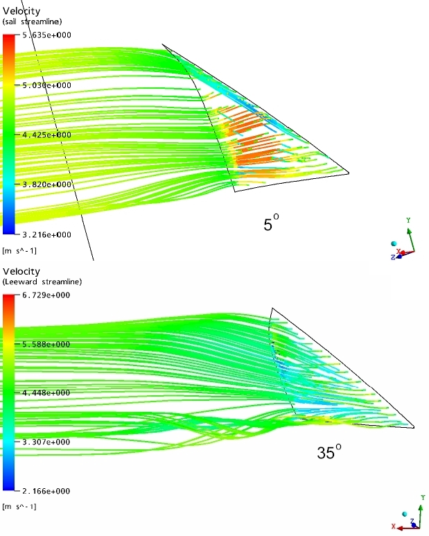
Figure 9:
Streamlines with the sail set at 5ş (above)
and 35ş (below) to the airflow (from Ryan, 2007) |
|
Vortex
formation at the foot of the Flčche sail became particularly marked at
high angles of incidence. The vortex increases the drag of the sail
and reduces its efficiency. To simplify the calculations, the
interaction of the sail with the hull and water surface was not
included. If the gap between sail and hull can be minimised or -
ideally - closed, then vortex formation could be inhibited or
prevented. (This is sometimes known as the ‘end-plate’ effect. In
the 1980s windsurfers began to take advantage of the improvement in
performance that can be gained by ‘closing the gap’. They achieved
this by altering the cut of the lower part of the sail and by
adjusting the rake of the rig in use in order to close the gap.) The
Flčche sail has been shaped with the aim of keeping this gap as
narrow as possible, but in practice the size of the gap changes as
the sail is trimmed according to the course being sailed.
There are several ways in which the gap might be
effectively closed when using a Flčche-type rig out on the water.
One way would be to trim the sail to the course required, and then
slide the feet of the A-frame forwards to lower the spar supporting
the sail until the foot of the sail is as close to the hull as
possible. The A-frame can then be locked in this position until the
next change of direction. Another way would be to close the gap with
cloth extending from the foot of the sail to an attachment along the
midline of the hull. There would need to be some way of adjusting
the amount of cloth made available to accommodate changes in sail
trim, so perhaps a spring-loaded conical roller could be arranged
along the midline to take up any slack in the gap-closing cloth.
Rather than aiming to close the gap, it may be
possible to reduce vortex formation by adopting the strategy of the
Crab-Claw rig, using the vortex-inhibiting qualities of a concave
leech and a sweptback tip at the bottom of the sail as well as at
the top. |
|
|
Key characteristics of delta-shaped
sails
These studies involving full-sized prototypes and
computational modelling have shown that delta-shaped sails have
several characteristic properties:
 since they have a lower aspect ratio than most other sailing rigs,
they have a correspondingly lower centre of effort which in turn
results in a lower heeling moment for a given sail area (other
conditions being equal)
since they have a lower aspect ratio than most other sailing rigs,
they have a correspondingly lower centre of effort which in turn
results in a lower heeling moment for a given sail area (other
conditions being equal)
they can operate more effectively at higher angles of incidence than
other sails and have a delayed stall. This makes them tolerant in
use
other than when sailing close-hauled, the delta-shaped sails produce
a significant amount of upwards-directed lift in addition to forward
propulsion
tip vortices are minimised, although a large vortex develops at the
foot of the sail if it is not close enough to the hull or water to
enjoy an endplate effect. |
|
Aerodynamics of
delta-shaped sails
It is interesting to consider
the aerodynamics of delta-shaped sails and the related
truncated-delta forms. I have come to the belief that the tolerant,
efficient nature of these sails is due to the way that they guide
the airflow across their surfaces and then release it cleanly from
the trailing edge, particularly at the tip. These sail forms, and
also certain wing forms found both in nature and in certain types of
aircraft, have in common a conical geometry, and this results in
several desirable properties. As a consequence of their overall 3-D
form, conically-shaped sails seem able to manage the airflow
smoothly across both windward and leeward surfaces. With their
swept, slightly washed-out tips, and with the upper parts of the
sail curving to windward, they appear to have an ability to suppress
drag-inducing tip vortices. |
|
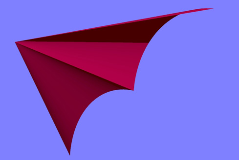
Figure 10:
The form of an early hang glider wing |
It is helpful to consider the geometry of early hang
gliders. The concept for these fabric wings was first patented in
1951 by Frances Rogallo (Messenger and Pearson, 1978). Each wing
consisted of a conical billow of cloth supported by the sweptback
leading edge and the midline fuselage tube (Figure 10). The
longitudinal axis of each billow halves the angle between the
leading edge and midline, converging on each side towards the nose
of the glider. Different parts of the wing have different angles of
incidence in relation to the approaching airflow, the regions close
to the midline having a more positive angle of incidence, and the
regions towards the wing tip having reduced angles of incidence.
(This is sometimes referred to as ‘washout’. It is comparable to
‘twist’ in the upper parts of a sail.) |
|
This simple geometry provides stability around all
three major axes (pitch, yaw, and roll). Thus, if the wing is
perturbed in flight, it will automatically dampen the perturbation
and return to stable flight. (Stability is enhanced by placing the
pilot below the wing and thus lowering the overall centre of gravity
to give added pendulum stability. The more recent hang gliders have
reduced sweepback and double-skinned wings that have a thicker
aerofoil section to improve performance.)
|
|
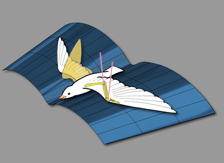
Figure 11:
The variable conical geometry of a bird’s wing –
the axes (pink) of the joints at the elbows and wrist
are principally normal to the imaginary conical surface
shown in blue. As the wing flexes and extends,
this conical form is maintained |
The wings of birds that are efficient gliders
generally have washout (increasingly negative angle of incidence)
towards the tip, and the tip is commonly directed downwards (anhedral)
and backwards (sweep). This was first noted by the pioneer of flight
Otto Lilienthal (1889). During development of the Transition Rig
(Dryden, 2004), my studies of bird wings (for example: those of the
gull) indicated that their wings also conformed to a conical
geometry (Figure 11). Thus they can be considered as truncated
deltas, conforming to part of a conical surface. I found that in
general the axes of the wing joints were set normal to such a
surface (plus or minus a limited range of movement for control
during flight), allowing the conical form to be maintained as the
wing flexed, extended, and folded (Figure 11). |
|
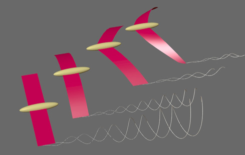
Figure 12:
Hypothesis: tip-vortices produced by different
wing configurations – straight wings produce large vortices (left);
anhedral wings produce smaller vortices (second left);
sweptback anhedral wings produce smaller vortices still;
sweptback anhedral wings with washout produce
minimal tip-vortices (right)
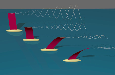
Figure 13:
Hypothesis: tip-vortices produced by different sailing rig
configurations – a vertical wing sail (back left) produces a large
vortex;
a vertical wingsail that curves to windward produces a smaller
vortex
(second from left); a wingsail that both curves to windward
and is also sweptback has a reduced tip-vortex (third from left);
a wingsail that is curved to windward, is sweptback,
and twists so that the tip is at a reduced angle of incidence
in relation to the apparent wind has the smallest tip-vortex,
and hence, drag (right)
|
To
generalise, it appears that there is something beneficial about
arranging the tip of a foil – either sail or wing – with a curve
towards the high pressure side (i.e.: windward side of sail, or
underside of wing in normal flight), swept backwards, and with a
reduced angle of incidence (wings - Figure 12, sails – Figure 13).
Presumably this configuration limits the spillage of air around the
tip of the foil and thereby minimises vortex production and drag. It
is my impression that delta and truncated delta rigs benefit from
this arrangement. This is a working hypothesis that it would be
interesting to test.
There has
been a continuing discussion about the Crab-Claw rig. In most
respects, the Crab-Claw conforms to the definition given above for
delta-shaped sails, the main difference being that the longitudinal
axis of the rig can be tilted to different angles in the vertical
plane according to the course being sailed. This means that the foot
of the sail is not always parallel with the surface of the sea.
Marchaj (1996) presented evidence from wind tunnel tests of models
that the Crab-Claw was much more efficient than more commonly used
rigs such as the Bermudan, particularly at high angles of incidence.
He suggested that this was due to the formation of leading edge
vortices on the leeward side of the sail which increased the lift
being generated, rather like the wing of Concorde when flying at
slow speed and a high angle of incidence. More recently, Slotboom
(2005a, 2005b) has questioned this analysis and proposes that the
efficiency of the Crab-Claw is due to optimal camber and angle of
incidence of the sail in its different positions. |
|
On the basis of my experience with delta-shaped sails
and the foregoing discussion, I would add that the Crab-Claw rig
probably generates minimal tip vortices both at the top of the sail
and the clew, and that this contributes to the rig’s efficiency. The
numerical simulation of the Flčche rig by Ryan (2007) did indeed
show vortex generation along the foot of the sail that became more
marked with increasing angles of incidence, and this may lend
support to the view of Marchaj (1996) with regard to leading edge
vortices, but the simulation showed that vortex production resulted
in a rapid increase in drag as the sail approached the stall, so it
seems unlikely that this mechanism accounts for the overall
efficiency of the Crab-Claw rig. |
|
|
Conclusion
|
|
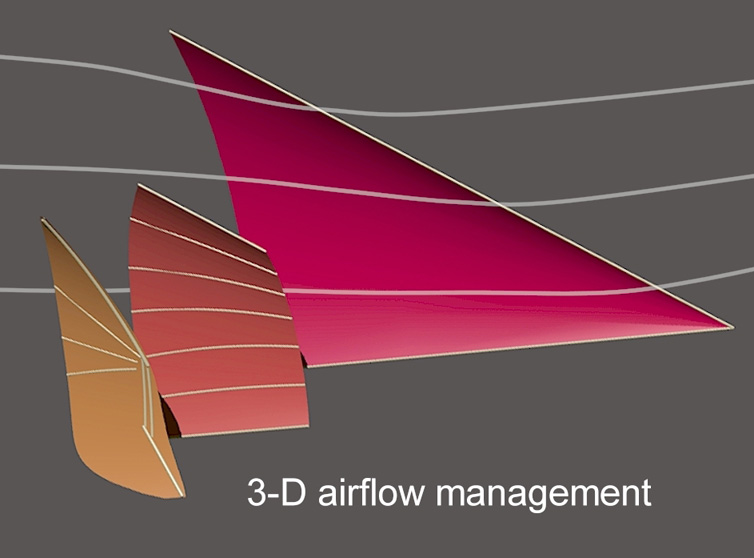
Figure 14:
A delta-shaped sail (back right) and two truncated deltas –
the Transition Rig (front left) and Junk Rig (mid position).
The airflow across the delta-shaped sail
is suggested by streamlines
|
|
|
References
‘Awesome Aussie Skiffs’
(1 and 2) Ronstan. Australia: Front Lawn Productions (videos).
Dryden, R. (2004) Transition sailing rig. Catalyst,
18, 14-20 (October).
Lewis, O.T. (2003) A search for effectiveness.
Catalyst, 11, 7-8 (January).
Lilienthal, O. (1889) Birdflight as the basis of
aviation. Hummelstown, A: Markowski International Publishers
(reprinted in 2001).
Marchaj, C.A. (1996) Sail performance: theory and
practice. London: Adlard Coles Nautical.
Messenger, K., and Pearson, R. (1978) Birdmen: A
guide to hang gliding. London: Corgi Books (pvii).
Ryan, A.J. (2007) A study into the efficiency of the
Flčche sail design, with use of computational fluid dynamics.
Thesis, University of Plymouth (April, 55 pp).
Slotboom, B. (2005a) A new analysis of the Pacific
Crab Claw rig. Catalyst, 22, 15-17 (October).
Slotboom, B. (2005b) Delta sail in a “wind tunnel”.
http://www.multihull.de/technik/t-slotboom_gb.htm (downloaded
14/01/2005). |
|
     
|