The Transition
Rig is a mast and sail that takes inspiration from
Nature, particularly the wings of bats and birds.
The mast is jointed, and this gives the rig a
capacity for variable geometry.
There are two
main reasons for developing this idea:
a variable
geometry sailing rig has the potential to adapt
to changing wind conditions, in the same way
that a bird can adjust its wing shape when
gliding in gusts and lulls and during flapping
flight
the
jointed mast allows the whole rig to be folded
away when not required, which is convenient and
also in stormy conditions may enhance survival.
Although the
concept is a relatively obvious one in the sense
that we see successful biological solutions to
variable geometry wings around us every day, the
Transition Rig is still at an early stage in its
development. I have numerous prototypes that
demonstrate different aspects of the idea and these
are described in these pages, but there is not yet a
fully-functional version that makes the most of the
variable geometry approach. I hope that this website
will give an insight into the potential of the
concept and offer a few solutions that I have found
to problems that arise when making variable geometry
sailing rigs. I shall be delighted if you can build
on these ideas.
Here is a short film made in the year 2000 giving an
overview of the Transition Rig idea:
The following is a broad overview of the
Transition Rig concept.
This was first published in Catalyst (the Journal
of the Amateur Yacht Research Society),
volume 18, pages 14-20 (October
2004).
Summary
The transition sailing rig takes its inspiration from the wings
of bats and birds. It can change shape in use according to
changes in wind strength, and can be folded into a convenient
bundle when not in use. The idea arose in 1986,
and I made a series of windsurfing prototypes in the years that
followed. From mid-2000 I was funded for one year by NESTA (the
National Endowment for Science, Technology and the Arts), and I
now have working versions of the rig for canoes, kayaks,
windsurfers, and dinghies.
variable geometry wings
The
concept
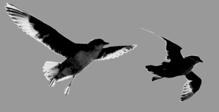
I
have always enjoyed watching birds such as gulls as they slope-soar
along hill sides and cliff faces, fascinated by the way they can
alter the geometry of their wings to cope with gusty conditions. In
light airs, their wings are fully extended, while in gusts their
wings are drawn in closer to their bodies and the outer segments of
the wings become more sweptback.
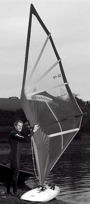
In the 1980s I developed a passion for windsurfing in the warm
conditions of Papua New Guinea. As a hobby I began to make
specialised sails and boards for speed sailing. I soon discovered
that each sail worked most effectively over a rather narrow range of
wind speeds. At that time we did not appreciate the value of
additional roach and controlled twist in the upper part of the sail
which now gives contemporary windsurfing sails a wider wind range.
The combination of an unforgiving sail and unsteady wind greatly
reduced the chances of sustaining a good speed over worthwhile
distances. It was then that I began to wonder whether it would be
possible to make a sailing rig that would be more adaptable to the
changing conditions encountered on the water.
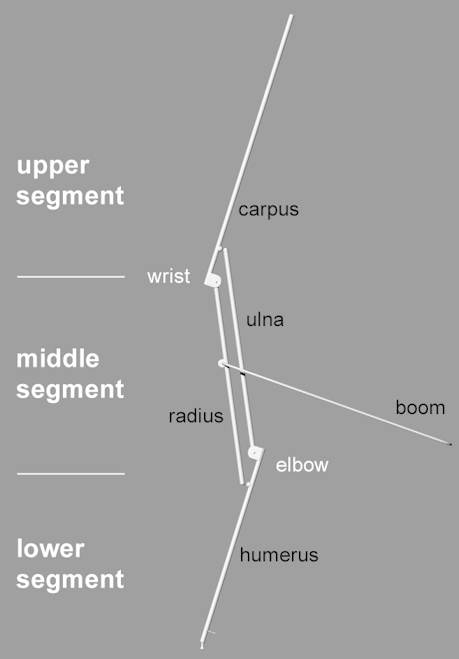
the main components and their names
The idea of making a variable geometry rig came in 1986. Although
the original inspiration came from the shape changes I had observed
in birds’ wings, I felt it would be more practical to follow the
structural example of the bat’s wing, where the flight surface is an
elastic membrane rather than overlapping flight feathers. This
approach would simplify construction and experimentation, and had
the added benefit of making it easier to reverse the aerofoil when
changing from tack to tack.
The jointed mast would have three segments: the lower one attaching
to the sailboard would be a single strut, the middle segment would
consist of two parallel struts, and the upper one would be a single
strut. This mimics the arrangement of the skeleton in bats and
birds, as well as in our own upper limbs. As a biologist, I quickly
fell into the habit of naming the parts of the rig in the way that
the biological equivalents are named. Thus, the lower segment became
‘humerus’, the middle struts became ‘radius’ and ‘ulna’, and the
upper segment became the ‘carpus’. (Carpus means wrist, so the use
of the term here is not accurate - other bones such as the
metacarpals and phalanges contribute to the skeleton of the tip
segment of a bat’s or bird’s wing.) The two middle struts (radius
and ulna) co-ordinate the movements at the upper and lower sets of
joints - as the ‘elbow’ flexes and extends, so must the ‘wrist’.
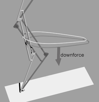
downforce on the boom flexes the mast
The main aim of having a variable-geometry rig was to use it fully
extended in lighter winds, and then flex the rig in stronger winds
so that the centre of effort of the sail was brought lower and the
upper segment of the mast made more sweptback. This I believed would
make the rig more effective and more controllable over a wider wind
range than a conventional rig, adapting better to gusts and lulls.
In the context of windsurfing, I envisaged that these adaptive
changes would occur in response to changing loads placed on the boom
by the sailor. In light winds, the sailor stands more upright on the
board, putting very little downforce on the boom, while in strong
winds, the sailor hangs most of their bodyweight from the boom to
counterbalance the lift generated by the rig. Part of that increased
load would be experienced by the boom as a down force, and this
could be used as a controlling force to bring about the
shape-change.
An additional advantage of a jointed rig is that it can fold into a
compact bundle for transport and storage, without the need to
dismantle any of the components. Thus, rigging and de-rigging can be
achieved rapidly and conveniently.
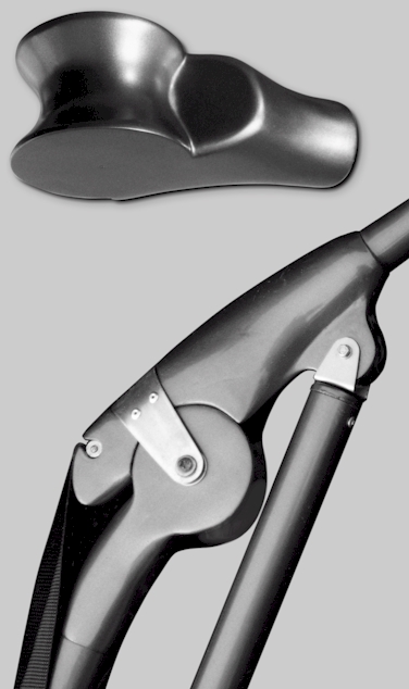
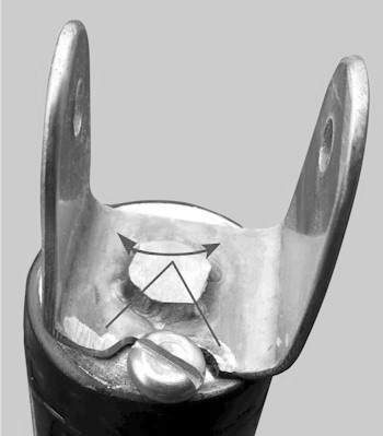
biology-inspired joints
the tensioner passes in front of the upper joints
and behind the lower joints
The
joints and tensioner
At first, my approach to joint-making was also influenced by
biological structures. I made the hinge joints from glass- and
carbon-reinforced epoxy resin, using large bearing surfaces with a
saddle (concavo-convex) shape. These components were time-consuming
to design and make, requiring the preparation of wooden blanks and
the intermediate step of mould-making, but when completed had the
advantage of being very resistant to the twisting forces they would
experience in use without being unduly heavy. From start to finish,
each generation of mast development would take about a year. More
recently, I have started to use much simpler metal joints which can
be made and modified comparatively quickly, and this has speeded up
the development process.
The first prototype was crude and was never tried on the water, but
it did enable some of the practical problems to be worked out. For
example, for the mast to change shape in the required way, it has to
be elastically tensioned so that it is fully extended when rigged
with the sail, and then begins to flex when downforce is applied to
the boom. I found a way to direct tensioning webbing around the
front of the upper joints and around the back of the lower joints,
making it adjustable at the foot of the mast. This made it possible
to balance the various forces acting on the rig and also make
allowances for sailors of different weights. Releasing the tensioner
completely then allowed the rig to be fully folded.
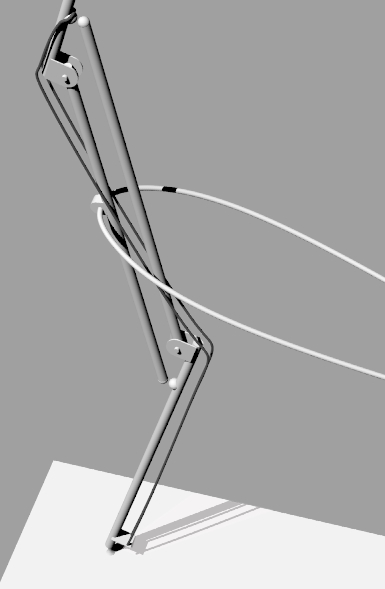
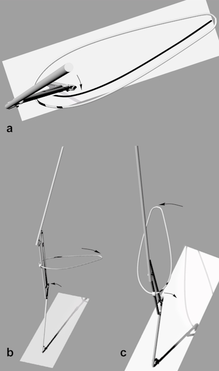
the pronation/supination rotation occurs between
the upper
and lower parts of the mast
the joints at the upper end of the ulna and lower
end of
the radius allow the pronation/supination movement
The basic geometry of the mast, the control of flexion and
extension, and how to achieve folding were worked out through trial
and error, but I found that many design problems still remained. For
example, the lower joints of the mast forming the elbow are set back
from the leading edge of the lower part of the sail at about 1/3rd
of the chord. This is a part of the sail that benefits from having a
good aerofoil section to produce power lower down. To achieve a good
section, the lower joints need to be displaced to leeward - away
from the sailor - on each tack. If the mast can only flex and
extend, this is not possible and the shape of the lower part of the
sail is compromised.
It was not too difficult to achieve the necessary rotation - I
followed the solution provided by the arrangement of our own forearm
and the forearms of birds and bats. If, in addition to flexion and
extension, the radius is able to rotate around its long axis at the
lower end in relation to the humerus, and if the ulna is able to
rotate its long axis at the upper end in relation to the tip segment
(carpus), then the lower joints can swing from side to side in
relation to the boom when tacking and gybing. The axis of rotation
for this movement passes between the universal joint at the lower
end of the radius and the universal joint at the upper end of the
ulna. The interesting thing about this arrangement is that the boom,
radius, and carpus work together as one unit, while the ulna and
humerus work as another unit during these pronation/ supination
movements. The rotation produces an interesting ‘cupping’ effect on
the overall form of the rig, where the carpus leans slightly to
windward in relation to the humerus. Before trying this system of
joints in practice, my belief was that the correct rotation would
occur automatically when the lower part of the sail ‘powered up’.
This turned out not to be the case.
(There is more about
pronation and supination here.)
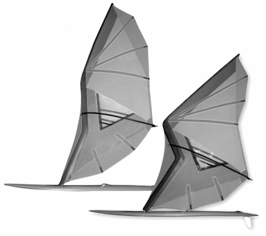
shape changes - rig extended in light winds
(left)
and more flexed in strong winds (right)
a sail made entirely from stretch materials
The sail
The next challenge was to make a sail that could accommodate the
shape-changes – flexion and extension, pronation and supination when
going from tack to tack – and at the same time keep a good
aerodynamic shape. Here I was faced by a dilemma: conventional
reasoning and experience say that if you want a sail to remain
stable, particularly in higher winds, you need to use a sail
material with minimal ‘give’. Indeed, one of the main thrusts in the
development of contemporary sailcloth has been to reduce stretch
under load.
As with many design problems, the trick is to find the correct
balance between apparently opposing requirements, in this case shape
change and aerodynamic stability. One of the main concerns with this
type of rig is that as the mast flexes, the tension in the trailing
edge of the sail (leech) becomes less. Within limits this is
acceptable, since it allows the upper part of the sail to ‘twist
off’ in stronger winds and reduce the power being produced. However,
if the leech becomes too loose, the rig becomes difficult to
control.
Early prototype sails made from stretch materials such as Lycra and
Spandex worked reasonably well in the sense that they allowed
shape-changes over a useful range while remaining reasonably taut,
but they were unsuitable for a sailing application. The porous
nature of the cloth allowed air to flow at least partially through
the sail from the windward to the leeward side rather than flowing
around it, greatly reducing its power, and if the cloth came into
contact with water it became saturated, baggy and heavy.
The next step was to experiment with stretch fabrics coated on one
side with a thin elastic film of polyurethane. These fabrics
fulfilled many of the requirements that I had for an elastic sail
cloth. They are lightweight, stretchable, tear-resistant,
UV-resistant, available in a wide range of colours, and airproof.
Their big disadvantage was that the fabric exposed on one side still
absorbed appreciable quantities of water. However, the single-coated
fabrics were good enough for the prototype sails to be tested on the
water. In some sails, I laminated two layers of the single-coated
cloth together so that the coated surfaces faced outwards, but this
proved to be a time-consuming process and even then water was able
to infiltrate between the laminations over time.
For several years I searched for a double-coated stretch fabric that
would overcome the water logging problem. Technically, double-coated
cloth is harder to manufacture than single-coated, and coating
specialists were not prepared to experiment on my behalf without a
substantial guaranteed order, which I was unable to provide.
Eventually a double-coated material became available - it had been
developed for use by the health service on operating tables and
trolleys.
For windsurfing it is helpful - and safer - to have a see-through
sail so that you can see where you are going and avoid collisions. I
had searched in vain from the beginning of the project for a
transparent and stretchy material, and had to make do by inserting
windows made of non-stretch clear plastic into the prototype sails.
Then, by a stroke of good luck, an article about the transition rig
was published in a science magazine and I received a useful tip from
one of the readers - a clear elastic film had been developed for use
in the female condom, and might have the required properties. Of
course, for sails a much thicker gauge of film is required, and
fortunately this was also available. The material has proved to be
very useful, fulfilling most of the criteria for a clear, stretchy
sailcloth. It does however have two disadvantages - it is very
difficult and frustrating to sew because it clings tenaciously to
the sewing machine’s flat surfaces, impeding its passage through the
machine, and it is also quite vulnerable to puncturing. In time I
hope to replace sewing with heat welding, and it may be possible to
incorporate a puncture-resistant mesh in the film, but for now the
film provides a step towards finding the ‘ideal’ material.
By now I was regularly testing the prototype windsurfing rigs on the
water, and repeatedly being reminded of the gulf between theory and
practice. One by one my assumptions and pet ideas were being
severely challenged. The pronation/supination movement gave the
biggest headache. As soon as the sail powered up, the lower joints
would flip across, but always in the wrong direction. Instead of
moving away from the sailor on each tack, they would do the
opposite, moving forcibly towards the sailor and giving the rig a
very un-aerodynamic shape. I tried many different systems to produce
the correct movement and lock the rig in the required shape, and
although some worked reasonably well, none of them gave a simple
automatic rotation when changing tack. I had hoped all along that
from the sailor’s point of view the transition rig would be used
just like a conventional rig, with all its variable-geometry
features looking after themselves automatically, and yet now I was
having to fit additional controls. A compromise solution did
eventually present itself, and now ensures that the correct rotation
occurs without the need for levers and locks.
(For more on this click here.)
raising the rig on a Mirror dinghy
Free-standing version
Up until 1999, my attention was focused on developing a variable
geometry windsurfing rig. However, my involvement as a volunteer on
a nearby project to build an ocean-going catamaran caused me to
think about how the transition rig idea might be adapted for use as
a free-standing rig and applied to other types of craft. With the
help of friend and colleague Alex McCall, a Mirror dinghy was
modified to accept a cable-operated folding mast and sail. The most
complex engineering occurs in the region of the mast foot, which has
to be strong enough to support the unstayed rig, be free to rotate,
and also allow the passage of multiple control cables close to the
axis of rotation. The rig incorporates all the movements described
above and has an additional control to allow tuning of leech
(trailing edge) tension when the rig takes on different shapes. The
steel cables for raising, lowering, and rotation are attached to
horizontal levers beneath a false floor in the dinghy and operated
by blocks and tackle. This version of the rig has come the closest
yet to fulfilling the different aspects of the original concept.
(For a video click
here)
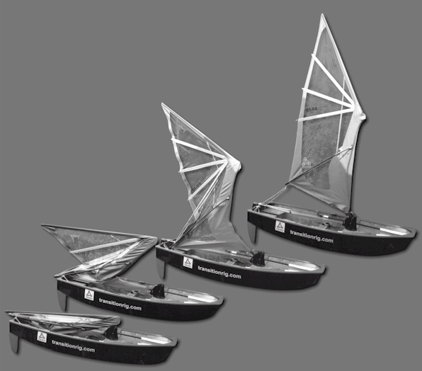
Simplified versions of the free-standing rig have also been
developed for smaller craft such as canoes and kayaks. These offer
umbrella-like convenience in that they can be raised quickly when
required, and folded away into a small bag when not required and
stored out of the way. However, these smaller rigs do not have the
capacity to change shape according to conditions - they are either
fully extended or folded.
Having worked out the arrangement of a free-standing version of the
transition rig and the control systems required, it then became
possible to propose folding rig modules for larger ships. Tankers
and some bulk carriers have significant areas of relatively free
deck space, and it may be possible to provide sails as a way of
reducing the amount of fuel they use. Even a 15% reduction would be
worthwhile, given that oil is a finite, diminishing resource and
that the burning of heavy fuel oil has a harmful effect on the environment.
Folding, removable sail modules bring several advantages over fixed
masts and rigging, and one of my ambitions now is to generate enough
interest in the concept to be able to build a working prototype for
testing. (For more on this, click
here.)
transition
In conclusion
The transition rig changes shape as it adapts to different
conditions, being fully extended in light conditions and more flexed
and streamlined in heavy conditions. Added to this is the
convenience and safety of a rig that can be folded away when not
required. These advantages come at a price – the rig is more complex
and will require good design and materials if it is to match the
strength and durability of conventional rigs without a significant
weight penalty. And with complexity comes the potential for
increased cost, at least in the early stages of development.
The variable geometry approach to sailing rigs offers an alternative
pathway for development compared with more traditional rig designs.
The name ‘transition’ was chosen for this concept because it implies
both the evolutionary transition and the shape changes in use.