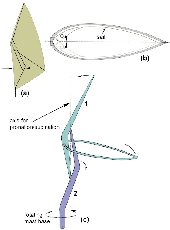
Pronation and
supination are rotational movements that occur within the Transition Rig.
The Transition mast has a zig-zag shape when
it is extended, and the joints between the lower and middle segments
are set back some distance from the leading edge of the sail. For the lower half
of the sail to set correctly, the lower joints have to swing away
from the midline
towards the leeward side of the boom on each tack.
a) the lower joints of
the mast are set back from the leading edge of the sail
b) when changing tack, a
rotation has to occur so that the parts of the mast below the boom
move across towards the leeward side. This enables the sail to take
on the correct camber.
c) the best way to
visualise this pronation/supination movement is to think of the
upper part of the mast, the front middle segment, and the boom
forming a single unit (labelled 1). The back middle segment,
and the lower part of the mast form another unit (2). Joints
at the bottom of 1 and the top of 2 allow the two units to spin
around a vertical axis in relation to each other (the axis for
pronation/supination). When the top of the mast and the end of the
boom move away from us, the middle part of 2 moves towards us. This
internal rotation of the mast is different from the rotation of the
mast base when the rig is being sheeted in or out when sailing.
I have summarised below
some of the ways in which I have implemented this rotation in dinghy and windsurfing rigs.
Pronation and supination add to the aerodynamic effectiveness of the
Transition concept, but at the same time add to its complexity - an
additional control function is required. However, while developing
the prototypes I have found an alternative, simpler, way of moving
the lower mast joints automatically in the correct direction,
although at the price of a slight loss of effectiveness. I shall
describe this alternative solution also.
Here
is a short video showing how the pronation/supination movement was
originally implemented on a Mirror dinghy. This was the earliest
free-standing version of the Transition Rig, and the mast uses
biology-inspired joints. It was made in 2000. More recent dinghy
rigs have a simplified structure.
The first Transition Rig
prototypes were made for windsurfers, and my initial assumption was
that if I incorporated the necessary joints, then the correct
pronation/supination rotations would occur automatically when
tacking and gybing. (For a description of the
joints that allow pronation and supination to occur, please click
here.) I visualised that the positive air pressure on
the windward side of the sail would be enough to swing the lower
joints across to the leeward side. Out on the water, I soon
discovered that the opposite was true - as soon as the sail powered
up on a given tack, the lower joints flipped across to the windward
side, that is to say, the wrong way. This gave the lower third of the sail a very poor aerofoil
shape. Pushing the joints to leeward took some effort and they would
soon flip back to windward. On reflection, I realised that the force
for this
contra-rotation was being generated by the upper part of the sail,
which has approximately twice the area of the sail below the boom.
The top segment of the mast was being pushed away to leeward, and
this resulted in a force on the lower joints to windward. I then had
to find ways of overcoming this problem. I was looking for a method
that caused the least distraction for the sailor, who when
windsurfing already has their hands full, quite literally - it is
not good to be trying to force an unwilling rig to adopt the right
form when also trying to harmonise all the other forces at work.
Here are three of the solutions I
tried for windsurfing rigs:
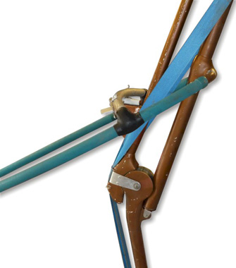
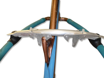
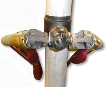
side view, showing cross-tube behind middle
mast struts
view from behind, showing roller attached to the
back of one of the middle mast tubes.
Two interconnected locks are in the open position
the lower mast joints can swing from side to
side,
with the cross-tube running on the roller
mast strut rotated to left and locked
Solution 1:
cross-tube
with locks (1999)
A
curving tube is attached across the boom, passing behind the rear
strut in the middle segment of the mast. A roller is attached to the
rear strut and the cross-tube can move from side to side, supported
on the roller, as pronation and supination occur. Two locks are
fitted, one on each side of the cross-tube, and they are interlinked
so that if one is opened, the other opens at the same time. They can
also be closed at the same time. When sailing, the downwards pull of
the sailor holding on to the boom causes that side of the boom to
tilt downwards slightly and the increased pressure of the curving
cross-tube on the roller forces the rear strut away from the sailor
towards the other side of the boom. When it reaches the stop, the
sailor can operate the lock to hold the mast in the correct
configuration until the next tack or gybe.
In practice, this arrangement
works quite well. It does however require manual operation of the
locks by the sailor who must remove one hand from the boom to
operate the lock.
There are, however, some
disadvantages. The cross-tube, locks, and roller all add weight and
complexity to the rig. If the boom is adjusted to allow for sailors
of different heights, then the roller support must be adjusted too.
The presence of the cross-tube means that there needs to be a hole
in the corresponding part of the sail to allow the tube to pass
through. This is not an ideal situation, because the hole will allow
equalisation of pressure between the windward and leeward sides of
the sail, reducing efficiency.
The next example eliminates the
need for a cross-tube.
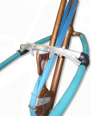
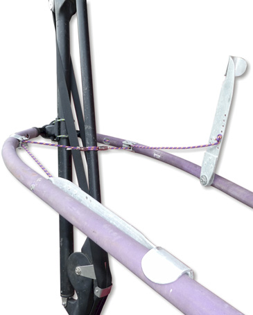
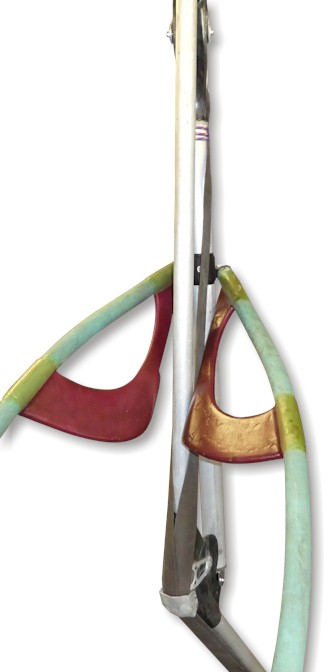
the left side lever has been rotated down and
locked,
tightening the rope attached to it and rotating the
rear middle segment to the opposite side
viewed from below - the ropes and pulleys
Solution 2:
levers and rope (1999)
In this arrangement, there is a
lever attached to each side of the boom. A rope from each passes a
pulley and travels through the inside of the boom, around the front
of the mast and to the other side of the boom. Here it passes
another pulley and is attached to the rear middle segment of the
mast. When the lever is pulled down to the boom, it tensions the
rope and pulls the middle segment to the other side. Because the
rope is attached below the level of the lever's pivot, the lever is
stable in this closed position.
When beginning a tack or gybe,
both levers are in the raised position to release the rear middle
segment. After completing the manoeuvre, the lever on the sailor's
side is pulled down to pronate the mast to the opposite side.
This system worked, but like
the previous solution requires a hole in the sail for the ropes
attaching to the mast. Care also had to be taken to avoid trapping
the fingers under the levers. Once again, this is not an automatic
system, and therefore not ideal.
The next example produces the required movement
automatically.
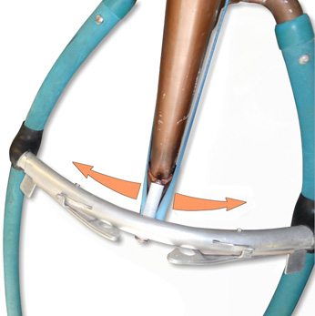
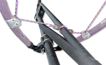
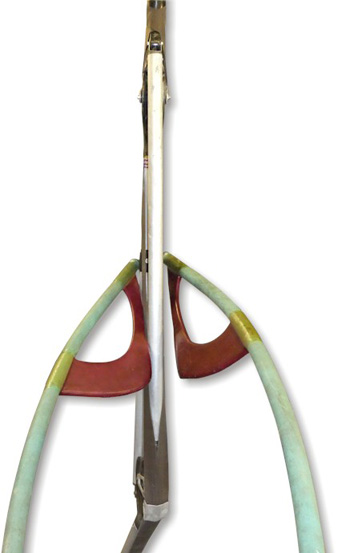
angled plates are attached inside the front end
of the boom
the attachment of the boom to the mast
allows the boom to tilt from side to side
the right side of the boom has tilted down,
and the plate is pushing the mast segment
to the left
the left side of the boom is tilted down,
and the mast segment is pushed to the right
Solution 3:
angled
plates attached to boom
(2001)
In this arrangement, pronation and supination are
carried out by tilting the boom and having angled plates push the
rear middle mast strut in the right direction. Tilting of the boom
is achieved by having a suitable attachment of the front of the boom
to the mast by way of a universal joint, and by the sailor putting
weight on the boom while sailing.
This set-up has three advantages
over the preceding one - there is no need for locks operated by the sailor, there is no need for a hole in the sail,
and the movements occur automatically.
However, the sail wears more quickly where the angled
plates press it against the mast segment during sailing. It also
requires modification of a standard boom.
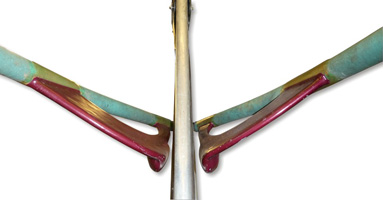
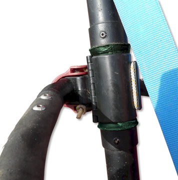
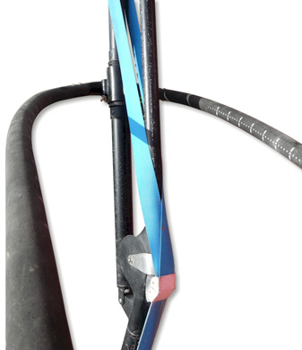
a rotating sleeve (green) is held in position
on the mast by two stops (above and below).
A standard boom is clamped to the sleeve
and the boom is free to rotate around the mast
the entire mast has been rotated to the right
in relation to the boom
c) compromise solution
It was always my intention to
make the Transition Rig as easy to use as possible, and I was not
happy with the complications being added by the need to move the
lower part of the mast to leeward when changing tack, particularly
when windsurfing. I decided to compromise, and experimented with
rigs in which the pronation/supination rotation within the mast was
eliminated, and instead the boom was able to rotate around the mast.
This was achieved by fitting a composite sleeve around the mast that
was free to rotate, and then clamping the boom to the sleeve.
With this arrangement, when the
sail powers up on the new tack, the forces in the sail swing the top
of the rig to leeward in relation to the boom, and the lower joints
have to follow suit. So the correct movement becomes automatic and
natural. However, a small price is paid in terms of aerodynamic
efficiency since the rig no longer "cups" to windward.
This compromise approach is to
be recommended if you want the simplest solution to the
pronation/supination issue - it is simple in structure and simple in
use. I am using this solution on my current windsurfing and
free-standing rigs.
d)
conclusion
To get the greatest aerodynamic
benefit from the Transition Rig, it is worth going to the trouble of
incorporating the pronation/supination rotation within the mast. This produces a "cupping" of the rig to windward
and improves its performance - as the lower joints move to leeward,
the tip of the mast moves to windward. However, this rotation adds
complexity, and requires the sailor to operate an additional control
- it is not automatic.
The alternative is to eliminate
the pronation/supination movement within the mast, and instead allow
the front of the boom to rotate in relation to the mast. Then the
movement of the lower joints to leeward becomes automatic, and an
additional control is not required. The cost of this simplification
is a slight loss of aerodynamic efficiency. The "cupping" effect is
absent as the top segment of the mast is now deflected slightly to
leeward.