|
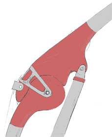 |
I was introduced to this technique of mould-making by Hans
Arkeveld, the renowned Australian artist. Thank you, Hans!
I use this method when making
biology-inspired joints for prototype Transition Rigs.
|
 |
|
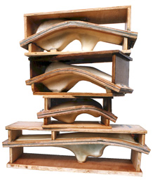
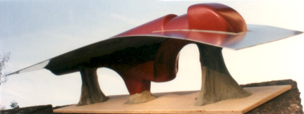
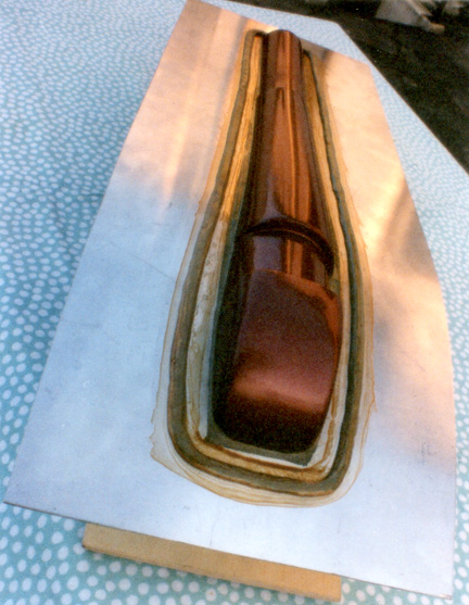
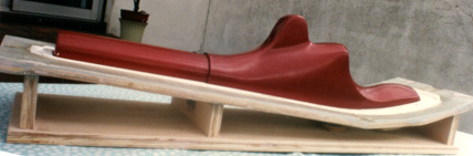
The first step is to make
full-sized patterns of the shapes that are to be moulded.
Usually I make the shapes from wood, coat them with epoxy resin,
and then paint them.
|
 |
|
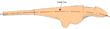
| The next step is
to decide the plane along which the mould will separate into two
halves. The position of this 'break line' will depend on the shape
of the pattern. (More complicated shapes may require a mould to
separate into more than two parts.) |
 |
|
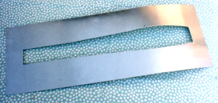
| There are
different ways to create a surface along this line, but for the
relatively simple shapes that I am using I cut out a piece of thin
aluminium sheet and then curve it to fit the break line. |
 |
|
| With the pattern
supported in a suitable position, the aluminium sheet can be held in
position with modelling clay (Plasticine�)
which is also used to fill any small gaps between the cut-out in the
plate and the pattern. |
 |
|
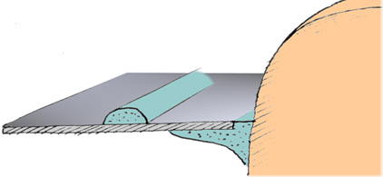
| A narrow strip of
modelling clay is placed on the metal surface about 2 cms from the
pattern - this will produce a ridge and corresponding groove in the
two halves of the mould, and help to key them together.
In the next step, silicone rubber
will be used. Silicone rubber does not set properly when it comes
into direct contact with modelling clay, so the exposed clay must be
painted with shellac. (Shellac is a fast-drying material made from
the wing cases of a beetle dissolved in methylated spirit.)
After two coats of shellac have
been applied and allowed to dry, a thin film of petroleum jelly
(Vaseline�) is smeared over the
shellac-painted and exposed aluminium surfaces. |
 |
|
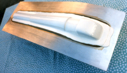
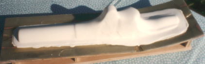
| Silicone rubber is
then poured over the pattern. I use Silastic E RTV�
by Dow Corning. The rubber is mixed with a catalyst in the ratio of
10 parts rubber to 1 part catalyst. This is a viscous material and
has to be coaxed to flow evenly over all the surfaces and fill all
the nooks and crannies. It takes approximately 24 hours to set at
room temperature.
After the rubber has set, it will usually be necessary to apply a
second and perhaps a third layer of rubber, depending on the size of
the mould being made. If the pattern has any sharp angles or other
potentially weak areas, the rubber can be reinforced with pieces of
glass fibre cloth placed in those areas and saturated with the
rubber. |
|
|
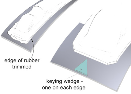
| When the rubber
has cured completely (about 2 days after the final coat) the edges
can be trimmed with a sharp knife so that the inner rubber mould
will fit snugly in the 'mother mould' that is going to be made next.
Also, triangular keying shapes made from modelling clay can be added
at this stage and painted with shellac.
The rigid mother mould will be
built up around the outside of the rubber mould to give it support. |
 |
|
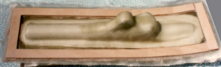
| Mother moulds can
be made from various materials. Perhaps the most convenient is
quick-setting Plaster of Paris, although the finished mould is heavy
and is breakable. I prefer to use glass fibre/epoxy resin composite
which gives rise to a light and strong mother mould.
A layer of petroleum jelly is
first applied to all the surfaces that will be in contact with the
mother mould. This will facilitate separation at a later stage. The
edges of the mother mould are built up first with narrow strips of
glass fibre cloth and resin butted up to the edge of the rubber
mould. Six to eight layers will be needed. Then glass fibre cloth
can be laid over the entire surface (rubber and edges) and saturated
with resin. Four to six layers of cloth will be enough.
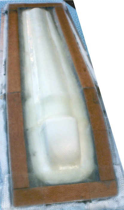
To further strengthen the edges
of the mother mould, add strips of plywood, using car body filler
paste as the adhesive to take up any surface irregularities. Then a
few more strips of glass fibre cloth can be added around the edges
to add further strength. |
 |
|
| To complete this
half of the mould, a wooden base is added to support the mould when
it is turned over.
This is a good time to trim the edges of the
half-mould with a saw to remove surplus glass fibre composite and
wood. |
 |
|
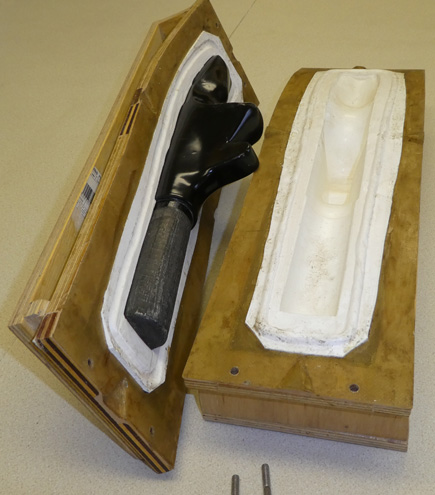
| The whole
work-piece can now be turned over and the temporary supports for the
pattern removed. The aluminium sheet for the break line can be
lifted off, and all traces of modelling clay removed.
The sequence is now repeated for
the second half of the mould. Petroleum jelly is smeared thinly over
the exposed surface of the first mother mould. The layers of rubber
are built up, reinforced where necessary, the edges trimmed, and
then the second half of the mother mould built over the form.
|
 |
|
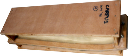
| Finally, a base is
added for this half of the mould, the edges are trimmed, and holes
are drilled for bolts that will clamp the two halves of the mould
together. |
 |
|
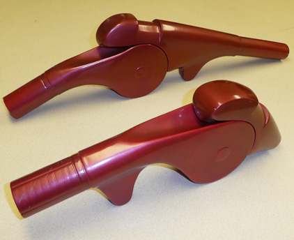
| The finished mould
can be used to make multiple copies of the original shape. In this
example, a thin coat of epoxy resin was applied to the inner surface
of both mould halves, allowed to polymerise, and then unidirectional
carbon fibre was laminated into the mould halves to build up a
sufficient wall thickness. A length of aluminium tube and a shaped
piece of wood were fitted internally for reinforcement, and then
before the resin polymerised the two halves of the mould were
brought together and bolted. The mould was then rotated to ensure
even distribution of the resin and effective fusion of the internal
components and the two composite halves.
After polymerisation, the joint
component can be removed from the mould and prepared for use. If
required, an expanding polyurethane foam can be injected into the
hollow core to fill it and add strength. |
 |
|
|
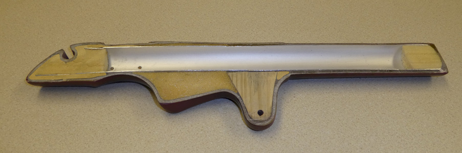 |
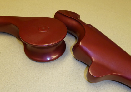
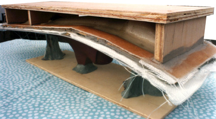
This joint
component has been sectioned longitudinally to show the
internal structure: the aluminium tube, shaped wooden
reinforcement, and foam filling.
|
|